Engineering ToolBox - enabled for use with the older versions of the amazing SketchUp Make and the newer "up to date" SketchUp Pro .
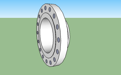
Dimensions, sizes and specifications of DIN 2637 Welding Neck Flanges PN100/100BAR

NB! If there is problem with inserting flanges - try to reinstall the extension by using alternative 3 as described in the right column.
Rotate the screen or widen the window to see full table!
|
Nominal Size mm |
Outside Diameter of Flange mm |
Diameter Bore mm |
Thickness of Flange mm |
Diameter of Raised Face mm |
Height of Raised Face mm |
Diameter of Hub at Base mm |
Diameter of Hub at Point of Welding mm |
Length through Hub mm |
No. of Holes |
Diameter of Holes mm |
Diameter of Bolts mm |
Diameter of Bolt Circle mm |
Weight kg |
|
|---|---|---|---|---|---|---|---|---|---|---|---|---|---|---|
| insert! | 10 | 100 | 10.4 | 20 | 40 | 2 | 28 | 14 | 45 | 4 | 14 | 70 | 1.07 | |
| insert! | 10 | 100 | 13.6 | 20 | 40 | 2 | 32 | 17.2 | 45 | 4 | 14 | 70 | 1.08 | |
| insert! | 15 | 105 | 16 | 20 | 45 | 2 | 32 | 20 | 45 | 4 | 14 | 75 | 1.19 | |
| insert! | 15 | 105 | 17.3 | 20 | 45 | 2 | 34 | 21.3 | 45 | 4 | 14 | 75 | 1.19 | |
| insert! | 25 | 140 | 24.8 | 24 | 68 | 2 | 48 | 30 | 58 | 4 | 18 | 100 | 2.61 | |
| insert! | 25 | 140 | 28.5 | 24 | 68 | 2 | 52 | 33.7 | 58 | 4 | 18 | 100 | 2.6 | |
| insert! | 40 | 170 | 38.7 | 26 | 88 | 3 | 65 | 44.5 | 62 | 4 | 22 | 125 | 4 | |
| insert! | 40 | 170 | 42.5 | 26 | 88 | 3 | 70 | 48.3 | 62 | 4 | 22 | 125 | 3.99 | |
| insert! | 50 | 195 | 50.6 | 28 | 102 | 3 | 86 | 57 | 68 | 4 | 26 | 145 | 5.72 | |
| insert! | 50 | 195 | 53.9 | 28 | 102 | 3 | 90 | 60.3 | 68 | 4 | 26 | 145 | 5.7 | |
| insert! | 65 | 220 | 68.9 | 30 | 122 | 3 | 108 | 76.1 | 76 | 8 | 26 | 170 | 7.43 | |
| insert! | 80 | 230 | 80.9 | 32 | 138 | 3 | 120 | 88.9 | 78 | 8 | 26 | 180 | 8.58 | |
| insert! | 100 | 265 | 98 | 36 | 162 | 3 | 145 | 108 | 90 | 8 | 30 | 210 | 13.02 | |
| insert! | 100 | 265 | 104.3 | 36 | 162 | 3 | 150 | 114.3 | 90 | 8 | 30 | 210 | 12.79 | |
| insert! | 125 | 315 | 120.4 | 40 | 188 | 3 | 180 | 133 | 105 | 8 | 33 | 250 | 21.29 | |
| insert! | 125 | 315 | 127.1 | 40 | 188 | 3 | 180 | 139.7 | 105 | 8 | 33 | 250 | 20.68 | |
| insert! | 150 | 355 | 144.8 | 44 | 218 | 3 | 210 | 159 | 115 | 12 | 33 | 290 | 28.9 | |
| insert! | 150 | 355 | 154.1 | 44 | 218 | 3 | 210 | 168.3 | 115 | 12 | 33 | 290 | 27.76 | |
| insert! | 175 | 385 | 176.1 | 48 | 260 | 3 | 245 | 193.7 | 127 | 12 | 33 | 320 | 36.94 | |
| insert! | 200 | 430 | 199.1 | 52 | 285 | 3 | 278 | 219.1 | 130 | 12 | 36 | 360 | 49.35 | |
| insert! | 250 | 505 | 242 | 60 | 345 | 3 | 340 | 267 | 157 | 12 | 39 | 430 | 81.71 | |
| insert! | 250 | 505 | 248 | 60 | 345 | 3 | 340 | 273 | 157 | 12 | 39 | 430 | 80.09 | |
| insert! | 300 | 585 | 295.5 | 68 | 410 | 4 | 400 | 323.9 | 170 | 16 | 42 | 500 | 116.25 | |
| insert! | 350 | 655 | 323.6 | 74 | 465 | 4 | 460 | 355.6 | 189 | 16 | 48 | 560 | 166.09 | |
| insert! | 350 | 655 | 336 | 74 | 465 | 4 | 460 | 368 | 189 | 16 | 48 | 560 | 160.53 | |
| insert! | 400 | 670 | 378 | 60 | 535 | 4 | 475 | 406.4 | 160 | 16 | 42 | 585 | 127.7 | |
| insert! | 400 | 670 | 390.6 | 60 | 535 | 4 | 475 | 419 | 160 | 16 | 42 | 585 | 122.13 | |
| insert! | 350 | 580 | 338 | 46 | 465 | 4 | 408 | 355.6 | 125 | 16 | 36 | 510 | 67.73 | |
| insert! | 350 | 580 | 350.4 | 46 | 465 | 4 | 408 | 368 | 125 | 16 | 36 | 510 | 63.96 | |
| custom! |
ISO and DIN dimensions.
Tip! - use the "Rotate Object" bellow to turn the object after it is inserted.
NOTE!! - the insert! and the Tools features only works when the engineeringtoolbox exension is opened from within SketchUp. Install the extension as described in the right column - restart Sketchup and open this tool from the Sketchup Plugins menu.
undo! redo!
change color!
Change color of the selected object(s) - may be slow for some more complicated objects (save your model first!)
iso! top! front! right! left! back! bottom!
make!
Makes a component of the selected object. Note that all objects from the Engineering Toolbox are inserted as individual groups. You should transfer a group to a component sharing the same definition when there is more than one instance of the same object. Tip! Rename the object to its final name before making it a component (in outliner or with right click and entity info).
around red! , green! or blue! axis.
Select object(s) first. This tool may be very handy for objects with curved surfaces like pipes, elbows and so on.
Move or copy (multiple) selected objects. Make advanced geometric constructions with multiple selections, multiple copies and the offset. Tip! - Use "Make Component" to save space and reduce computer load when working with multiple copies.
Before cut - customize the inserted Knife! The Knife is a group you can rotate, change the size of, and even add or remove objects within (example - add a function curve for an advanced cut). You can also make your own Knife by naming a group "theKnife". After insert and customizing the knife - positioning it to the object(s) where to cut - select the object(s) (must be groups) - and click cut! Afterwards - select the object(s) and remove the parts of the object(s) that you don't want. YouTube demo of the Knife!
Select two objects - click "move" - and one of the objects moves to the position and angle of the other object. This tool may be handy when moving objects between axis systems.
startpoint
endpoint insert!
This tool can be used to add reference lines.
We don't collect information from our users. More about
Insert standard and customized parametric components - like flange beams, lumbers, piping, geometric figures, function curves, stairs and more - to your Google SketchUp models with sketchup.engineeringtoolbox.com

It's FREE and FUN!
If you don't have Sketchup installed on your computer - download the older versions of the amazing SketchUp Make or the newer "up to date" SketchUp Pro
Note! - SketchUp Free and Sketchup Shop (the web apps) can't use extensions. You need to install a local version of SketchUp Pro (paid) or Sketchup Make 2017 (free) if you want to use the Engineering ToolBox extension.
From within Sketchup - open the Engineering ToolBox extension, navigate to component and select insert! - and the component will be added to your model.
Watch basic use of the Engineering ToolBox extension in YouTube
If you experience problems with the functionality - first try to reload the cached page with the link in the top left corner - then try installation with alternative 2 or 3.
Note! The Engineering Toolbox extension in Sketchup Extension Warehouse only works for Sketchup editions up to 2023. For Sketchup edition 2024 and higher the extension can be installed by using installation alternative 2 or 3 below.
Note that this procedure may be different in older Sketchup versions.
From the Sketchup menu - select Extensions > Engineering ToolBox. A page like this opens in a separate window - navigate to the wanted component - and select insert! to add the component to your SketchUp model.
Note! The SketchUp Engineering Toolbox is an online resource updated continuously. You need an internet connection to operate.
For some components parameters like length, color, offset and more can be modified before insertion.
Customized components can be inserted by changing parameters in the dialog boxes at the end of the component lists - and clicking "custom!"
Selected objects in the model can be manipulated - rotated, moved, colors changed and more - from the Tools section.
Assistant objects like lines, horizontal and vertical planes can be added.
The most efficient way to learn SketchUp is by watching the tutorial videos.
Organize your model in groups - add components to the groups!
Example: Use separate groups for construction steel, piping, the different HVAC systems
and more.
Always keep an eye on the model in the "Outliner" window.
Use layers to organize and control the visibility of the model.
The most convenient way to copy an object is by selecting it, using move or (m) and pressing Ctrl (makes a copy) before moving.
Use the rotation tool on this page to precise rotations of components like bends, pipes ...
Precise moving of a object can be done by selecting a point in the object that can be connected to a point in the new position (like a edge on a component, surface, a midpoint or similar).
Be aware that objects from The Engineering ToolBox are inserted in Sketchup as Groups. They will show up in the Sketchup > Window > Outliner dialog but not in the Sketchup > Window > Model Info > Statistics (Only Components) dialog.
If you want to make "Bill of Materials" from your model
The objects will now show up in the Sketchup > Window > Model Info > Statistics dialog and be available for reporting through Sketchup > File > Generate Report feature or other third party report generators.
An insterted object from The Engineering ToolBox can also be converted to a Component by right clicking the object and selecting Make Component. The name will not be preserved and must be changed after the conversion.
9 19